The Piezoelectric Effect
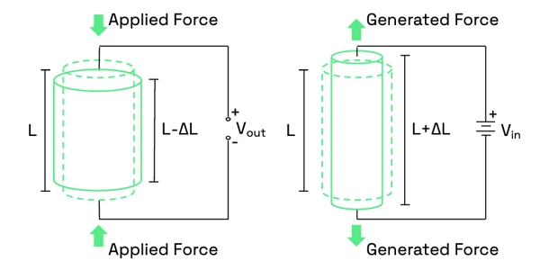
In 1880 Jacques and Pierre Curie discovered that pressure generates electrical charges in several crystals such as quartz and tourmaline; they called this phenomenon the piezoelectric effect. The word piezo is derived from the Greek word for pressure. Later they noticed that electrical fields could deform piezoelectric materials. This effect is called the inverse piezoelectric effect.
The Piezo LEGS® Technology
High precision
PiezoLEGS can without any problem position itself on a sub-micron level, or even down to the sub-nanometer range. The resolution of PiezoLEGS depends on the electronics used; the motor itself is not the limiting factor. With the ability to micro-step down to the sub-nanometer level, PiezoLEGS can achieve a truly smooth motion.
No backlash
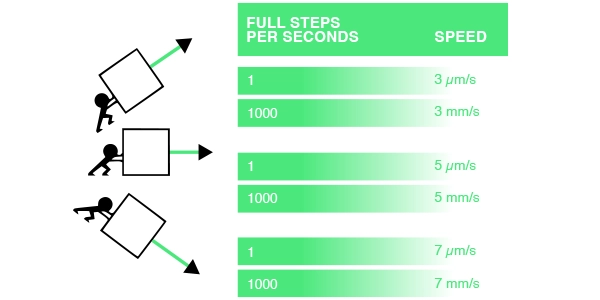
A controlled linear motion without backlash is achieved without the need for gearboxes or ball screws, as the motor responds instantly. This true direct drive enables a combination of high precision and a dynamic speed range. PiezoLEGS are self-locking and can hold load even when powered off.
By applying voltage to a piezoelectric material, you can induce shape changes in it. The ingenious design of the PiezoLEGS ceramic actuators allows each motor “leg” to be elongated or bent sideways. With the right drive signals, you can synchronize the movement of each pair of its four legs (or six), resulting in a walking motion akin to an animal’s – step by step, with the ability to stop at any precise moment. The direct friction coupling between the legs and the drive rod ensures that Piezo LEGS® operates without any backlash or mechanical play. Additionally, the direct drive provides full force, power-off locking without any power consumption.
Non-magnetic
The PiezoLEGS actuator unit is non-magnetic, which allows for the design of motors suitable for high-magnetic environments or situations where magnetic disturbances are a concern.
PiezoLEGS motors, unlike DC motors, are without windings and therefore don’t produce magnetic flux. Since stainless steel, the standard housing material, naturally ferrites, will disturb external magnetic fields, non-magnetic motors are available. These motors have housing and other parts made from non-magnetic alloys, making them compatible with use even inside an MRI machine without disrupting the imaging process.
Non-magnetic motors have a magnetic flux density of less than 1 nanotesla (sensor sensitivity in reference measurements) at a distance of 10 millimeters from the motor housing.
Compact designs
The compact design of the motors makes them ideal for OEM applications.
Acuvi utilizes the unique capabilities of PiezoLEGS to create high-precision actuators with direct drive. Unlike traditional solutions that require gears or mechanical transmissions, PiezoLEGS eliminates the need for these components. This results in backlash-free linear motion with nanometer or even sub-nanometer resolution. The reduction in the number of parts also leads to a significant decrease in the size of the motor compared to conventional solutions. Additionally, the simple drive electronics further contribute to space savings, enabling the miniaturization of any application driven by a PiezoLEGS actuator.
Using miniaturized PiezoLEGS actuators from Acuvi offers numerous advantages beyond improved resolution and instantaneous response. Notably, these actuators eliminate backlash and power consumption when the device is motionless.
Miniaturization, in addition to reducing complexity and decreasing motor dimensions, also entails size reductions for manufacturers. For instance, scaling down integrated circuits places a greater emphasis on precision in lithography processes. PiezoLEGS motors enhance accuracy to such an extent that new-generation integrated circuits are even more compact while still delivering superior performance. The semiconductor industry is at the forefront of innovation, just like Acuvi’s products.
We provide a range of standard motors, but the underlying technology is highly customizable. Don’t hesitate to reach out to our knowledgeable engineering team for expert advice.
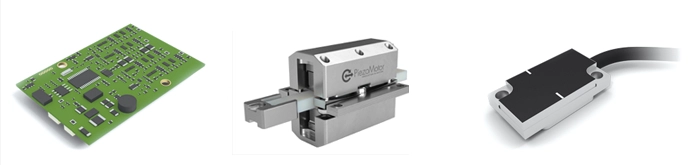
The system
To operate a piezo motor, you require drive electronics, which are essential in all modern motion control systems. The heart of the motor lies in a multi-layer piezo ceramic, a component renowned for its exceptional performance even at low voltage levels. By applying precisely controlled electrical voltage to the ceramic, a linear or rotary motion is generated.
To maintain control over the position, an encoder is necessary. The resolution of the system is determined by the encoder resolution and the electronics resolution.
One of the greatest advantages of piezo-based systems is their ability to achieve high precision and quick response times without incurring an increase in the system’s cost.
A piezo motor-based system employs a true direct drive mechanism, where the object to be moved is directly connected to the piezoceramic motor legs within the actuator through the drive rod. This design offers significant advantages, including the absence of backlash, rapid response times, and high resolution. Consequently, it enables short cycle times in repeated move-and-settle applications, thereby reducing overall processing time.
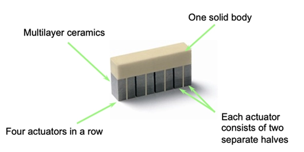
The Actuator
PiezoLEGS® operate using friction drive, where force is generated by the internal preload of the piezoceramic motor legs in direct contact with the rotor or drive rod. Consequently, the legs remain mechanically connected to the drive rod throughout their walking motion.
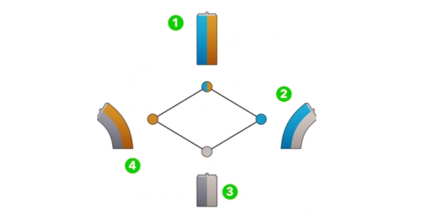
1. Voltage is applied to both left and right, causing the leg to extend to its fullest length
2. Voltage is applied to the left part of the leg, causing the leg to extend to the right
3. No voltage applied to the leg
4. Voltage is applied to the right part of the leg, causing the leg to extend to the left
Here you can see the sequence in motion:
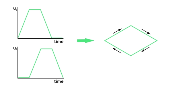
The electronics
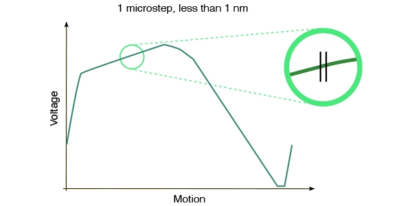
A controlled motion is created by applying a voltage signal to a ceramic leg. One for each side, u1 & u2. There are two version of the waveforms, as seen below. The step length varies depending on the load, as illustrated in the figure below. A single step can be divided into thousands of micro-steps, and the length of a micro-step can reach the sub-nanometer level.
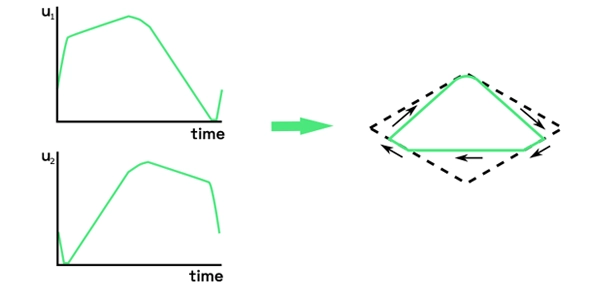
Waveform optimized for high micro-step resolution
A micro-step = a fraction of the waveform (full step); e.g. 8192 micro-steps per waveform.